A forest visualization project I’m working on in Unreal Engine (UE) requires some realistic looking terrain. I don’t really need specific terrain, just something that looks reasonable to stick under a forest.
I decided the best way to do this would be to import a LiDAR DEM into the engine and render the terrain surface using that. This is straightforward to do, but requires some c++ and a bit of GIS fussing to get everything working. Here’s a preview of the end product:
In this post I’ll describe the process required to get this working, and some of the considerations for using this sort of data. This is not a complete review of all the code used, just a general overview of the process.
The first step is to get the DEM. I downloaded one of the 10 x 10km sections of the provincial LiDAR derived DEM from the Mount Carelton area (Available here ). (Mount Carelton itself is in the upper left quadrant of the DEM, the lake in the top right is Bathurst lake)

Based on the hillshade, this DEM tile has a nice mix of lakes and hills, along with a few rivers/streams.
The files are provided in a GeoTIFF format which is easily read by something like QGIS, but needs a special importer to use in c++ (which we need in order to get the data into UE). Libraries like GDAL provide functionality to read rasters like this right in c++, but compiling those libraries with an UE project is messy. So I took a more circuitous route.
(Which, as it turns out, was slightly more complicated than just compiling GDAL, but it’s done now…)
I exported the TIFF out of QGIS as a .xyz file. This is essentially a text file with each cell of the DEM as an XYZ coordinate. A text file will require no special library to read, and will therefore play nicer with UE as we don’t need any third part libraries.
The file is too big to open in something like notepad, so I wrote a short python script just to peek at the values.

A couple of problems get revealed right away. First off, the DEM is in meters, UE units are equivalent to centimeters. The data as it stands needs to be converted. Also, the TIFF is in a coordinate system, so the coordinates for each cell don’t start at 0. In UE, we want our terrain to begin rendering at 0,0 and go from there, so the coordinates in the file will need to be adjusted.
Also, I was expecting the coordinates to be whole numbers, but you’ll notice they’ve all got a decimal of 0.5. Each record in the XYZ is the location of the center of a pixel, and since each pixel in the original TIFF was 1m by 1m this makes sense. Not a huge deal but something that will need to be addressed later.
Another issue (and one that I didn’t bother correcting because it’s not a huge deal) is how UE handles Y coordinates versus how a GIS does. In a GIS context, moving along the Y axis assumes that you are moving further north. In UE (and most computer graphics contexts) a movement in the Y direction assumes you are moving down the screen (0,0 in those situations is at the top left of your monitor). So, UE has a different idea of what direction south is compared to GIS.
What does this mean? Basically the DEM will be flipped when loaded into UE, that won’t hurt things, but it is something to keep in mind. To me at least, if you’re moving north (even virtually) you should be moving up the screen. Just hold your compass backwards I guess.
Now let’s get the data into UE.
I made a new component class called TerrainDataComponent. All this component does is store a reference to our DEM data, with a method for retrieving the value at a specific X,Y point.

This will allow any actor that has this component to query terrain data. Note that the elevations themselves are stored as a static variable. There is also a static bool to indicate whether the terrain data has been loaded from disk or not.
The idea here is to only have one version of the data loaded in memory at any time. Even though many different actors can have this component. The first time an actor with this component tries to access terrain data, that’s when it gets loaded. Because the bool is a static variable, every instance of this component will share the same instance of that variable, which ensures the data only gets loaded once.
And if any “real” programmers just dry heaved at how this is implemented as a singleton with an effectively global variable, I ask you: The terrain is literally representing the globe, so doesn’t it make sense that it’s a global variable? I’ll see myself out…
Below is how the terrain data gets loaded from the XYZ file.

I like a lot of things about c++. Reading text files from it is not one of them. You can compare the above to the roughly equivalent Python code earlier and see the difference.
Anyway, a few things are happening here. First, we are opening the file, and extracting three float values from each line (x,y,z). For the X and Y values we have to adjust them back to 0 by subtracting the minimum X and Y from them respectively. We do the same thing with the Z value. Since the minimum Z in the DEM is not 0, we subtract the minimum value so that the lowest point in our terrain will be 0.
The hardcoded values here are a problem, I know. Really you could just walk the file, find the minimum X,Y and Z and then do the adjustment while reading in the data again.
The data gets stored in the elevations array class member. This is a one dimensional array of float values. UE does not allow multi-dimensional arrays for its built in array types (TArray) and a one dimensional array has a smaller memory footprint. We can still access the data as if it was a two dimensional array, it just gets a bit more complex.
Basically, the array stores each row of data in sequence. We have 10,000 X values per row in our raster, so the first 10k indices of the array will correspond to those XY positions. The next row is represented by the next 10k indices and so on.
The X part of an XY pair tells us how far along a group of indices we are, and the Y tells us how many groups of indices (rows) deep to go into the array. If we know the X size of the array then this is trivial.
With the above code run, we now have all the terrain elevations loaded in.
The code above is agonizingly slow (one of the issues I alluded to earlier with doing this using an XYZ file). I suspect there’s a way to vectorize that operation and make it significantly faster, rather than looping through that file line by agonizing line. Ultimately this doesn’t affect the rendering performance, as we just need to load elevations one time. It does mean that initial load will be real slow though.
So I actually saved the elevation data into a UE savegame object, this way the XYZ file only needs to be run one time.

After creating this save game file one time, it can just be read in by the terrain component every subsequent time. This is much faster
Now we can actually render the terrain. UE has a robust, built-in landscape system, which is designed specifically for this purpose. It even includes features for streaming different parts of the terrain in and out of memory as needed (As the player actor moves around the world). There’s options for multiple levels of detail in terrain, so stuff farther away doesn’t render as detailed as parts close by. It also bakes custom collision, so no one falls through the ground.
We’re not going to use any of that.
Truthfully, the built in landscape system has way more functionality than I need here. Also, it doesn’t allow for certain things needed later on in this project (like rapidly querying terrain elevations at specific locations). The landscape system also assumes you’re pre-making your terrain before a project is packaged. You’ll notice in my setup, the terrain gets loaded at runtime. This allows for modification or loading different terrain during actual running of the project. Now I don’t need this at the moment, but having it is a bonus.
So I decided to build a custom terrain streaming and rendering setup that better meets my (less sophisticated) needs. UE’s landscape system probably offers better performance and more features, but this will do.
I do want a level of detail system (Higher res terrain closer to the player) so that needs to be implemented. The terrain will also need collision so that actors don’t fall through it.
I settled on using the Procedural Mesh Component for rendering and collision, and built a quad tree system to handle the level of detail. This wasn’t actually that much to implement.
Let’s start by talking about the Quad Tree. This will handle our level of detail system.
A quad tree is a way to recursively divide a 2d space. We start at the top of the tree and divide it into 4 equal squares. Then, for whatever of the 4 squares our actor is inside, we further divide that square. Then keep dividing until you reach some predetermined size, or number of levels. A quad tree works in two dimensions, the three dimensional equivalent is an octree (3d space divided into 8 cubes).

Now, each of these squares represents terrain to render. Each one has a fixed resolution that it renders at, say 10 vertices by 10 vertices. Since the squares closer to the player are smaller, those 10 vertices cover a smaller area which results in higher resolution terrain. Near the player we might have 1m resolution terrain, further out it could be 1000m resolution. High resolution (but expensive to render) terrain close to the player, low resolution (easier to render) farther away.
The quadtree is handled by a quadtree actor, that checks the location of the player, and then divides itself into 4 actors if the player is close enough, or renders terrain if they are too far. The child nodes then do the same test and divide until they get to the point where they render terrain.
Here’s the code that tests whether a quadtree node needs to divide itself:

Any actor can be passed in, allowing terrain to be rendered for either the player or some other object. Having terrain render for an actor is as simple as spawning a quad tree actor for them, and having the owning actor update the tree at the desired frequency.
One nuance you’ll notice here is that the distance is measured based on the location of this node’s children, not the location of the node itself. This is to cover edge cases, where the player is standing on the edge between two quads. This ensures that high resolution terrain is rendered on all sides of the player in those circumstances. If we didn’t do it this way, the player actor would have high res terrain on, say, their left side, and low res terrain on their right side, should they be standing to the left of the boundary between two nodes of the quad tree.
Now we can talk about actually rendering the terrain. (Incidentally these nodes are called “leaf” nodes. You can see why I picked this method. It’s got trees and leaves. Very forestry themed.)
As I mentioned this is done using the Procedural Mesh Component . The Proc Mesh is one of those hardcore components that exposes lowly gameplay programmers to the horrific underbelly of graphics programming. Scary stuff like tangents, vertex normals, uv channels, and collision baking.
Fair warning, there’s triangles too.
Basically the Proc Mesh gives you access to lower level rendering stuff (the scary sounding list of graphics terms I mentioned earlier). Give it a list of vertices, tell it how to triangulate those vertices, how to handle tangents and UVs and then you have a mesh.
All the details about how to render a Proc Mesh are out of scope for this post, but what I’ve done is query the vertices required for each quad tree, in the code below:

This takes the size of the quadtree, its location and the target resolution and gets this data from the terrain component (Where the DEM data is loaded). This is an array of FVectors corresponding to the points within that quad
This array of vertices is the first piece of data we need to render the proc mesh. The next is a list of triangles so the renderer knows where to put the faces on our mesh. The triangles are basically an array of integers, which reference the index of a given vertex in the vertex array. Each group of three items in that array correspond to one triangle.
Beyond the triangles, we also need vertex colors, UVs, tangents and normals for every vertex. These are created in separate arrays that parallel the vertex array.

I’m not doing anything fancy with any of these parameters (mainly because I’m not sure what most of them do…) so these arrays are just set to default values.
Then all this gets called to make our mesh

The only thing left to do is spawn a QuadTree actor and feed it our player location. The nice thing about this setup is the recursion handles everything down the tree, as long as the root of the quad tree is set up, everything is good.
And that’s it! We have a fully imported 10 x 10 km section of terrain in Unreal Engine. You can walk from one end to the other and new sections at the proper resolution will stream in and out.
There are some gaps visible in the terrain, especially far away. These are caused by mismatches between the resolutions of adjacent quads. You’ll notice some of these gaps disappear as the camera moves around. This is just a minor visual issue. Probably the easiest way to fix this would be to render some vertical terrain around the boundaries of each quad or maybe place a plane with the same material just below the terrain.
Here’s how it looks with some trees rendered onto it.
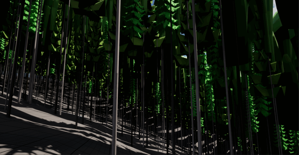
Those trees are loaded in from actual forest data and represent a 1:1 view of stand density, composition, DBH and height. That’s where this project is heading to, but this post was just to talk about the terrain.